
Digital Newsletter
Each week our editor Phil Alsop rounds up the most popular articles, videos and expert opinions. We compile this into a Digital Newsletter and send it straight to your inbox every week.
Digital Magazines
We'll let you know each time a new edition of Digitalisation World is released so that you're always kept up-to-date with the latest and greatest news and press releases.
Video Magazines
The Digitalisation World Video magazine contains the latest Zoom interviews with experts in the industry.
Managing increasing densities
Just a few years ago, an 864-fibre cable would have been considered a very large trunk. However, today fibre counts of 1728, 3456, and 5184 are common, with 6912 and 7776 fibres on the horizon. In combination with a lack of duct space, this has forced manufacturers to develop smaller cables. Innovations such as rollable ribbons have allowed more fibres to be packed inside of a cable. Manufacturers have also moved to 200-μm buffered fibres to pack 30 to 40 percent more fibre in cables. Designs that repackage flat ribbons into smaller diameters have appeared, along with cables featuring slotted cores or little or no bundle separation. As gel water block in a cable takes up too much precious space, most cables today are dry blocked.
Data centre operators are also figuring out ways to bring fibre into the facility. If a high-fiber-count cable lands directly inside a building, there’s no need for street access and traffic. This scenario also tends to be more secure and tamper-proof. Indoor rated cables can radiate from the cabinet and go directly to the top of the rack. Building entrance facility cabinets are now designed to be stacked vertically to allow for more splice capability.
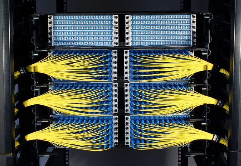
As rack space is valuable, high-density panels are now commonplace. Just a few years ago, a common fibre patch panel would be a static 4U offering containing 144 fibre terminations with SC duplex or 288 fiber termination with LC duplex adapters. Now, high-density offerings employing slides and special patch cables enabling port access are widely available. Panels with up to 240 fibre terminations for LC duplex per 1U have been introduced. Some users now favour MPO ports, bypassing the use of LC duplex terminations altogther. To reach the required high port density, panels are designed with sliding or swing trays. Cable slacks are captured in a cabling manager that ensures safe movement of the sliding tray for maintenance or extension.
New installation practices
Working with large-count rollable ribbon cables and panels requires a whole new set of skills and equipment. When breaking out a large-count cable, technicians need to be more careful, organized and aware of what they are doing. It is easy to mix up different fibre bundles when breaking out a 3456-fiber cable. A damaged fiber during breakout often requires the technician to start over.
Some companies offer tool-less fibre bundle sheath removal to help eliminate this problem. Once the fiber bundles are identified, they need to be furcated with a protective sock or tubing. These furcated fibre bundles need to be housed in a breakout kit, which will keep them protected from being twisted or kinked. Labelling fibres, furcated bundles and splice trays are all essential.
Working with high-count cables in data centres also requires different approaches. An installer will need more launch boxes and test cables and damaged test leads need to be replaced immediately to meet deadlines. The installer may consider using a fibre-optic switch in conjunction with their OTDR and OLTS to test MPO terminations.
The large number of ports that need to be tested often require additional test equipment and personnel. Many data centres do not allow recording devices to leave the facility, and prohibit test equipment with a cloud interface. A solution to this problem is for the test equipment to remain on site upon completion of the job. This creates calibration issues, and drives up the job cost. A partial solution may be to leave the test equipment mainframe and to remove the optical heads, which contribute significantly to equipment cost.